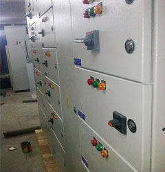
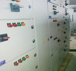
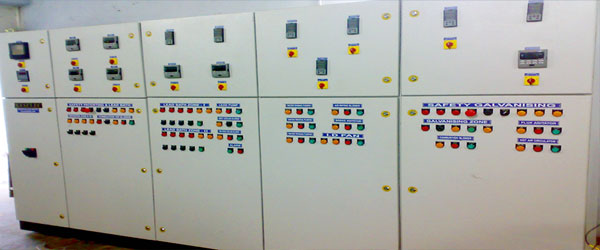
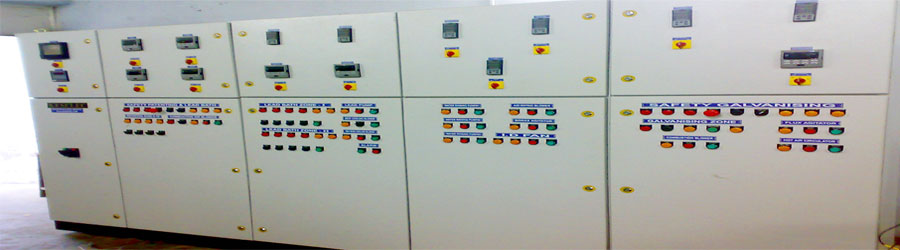
| Brief Description of Panel Manufacturing |
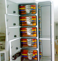
Our panels are factory assembled confirming to IS: 8623 with latest amendment. Cable entries and terminals are provided in the switchboard to suit the number, type and
size of aluminum conductor Power cables. Generous size of cabling chamber is provided with the position of cable glands and terminals such that cables can be easily
and safely terminated. Two distinct earthing bolts are provided on both the sides of panel to suit earthing as per IS Standards.
|
All steel material used in the construction of the switchboard undergo a rigorous rust proofing process comprising alkaline, degreasing, descaling in dilute sulphuric acid and a recognized phosphating process( 7 Tank Process). The steel work then receives
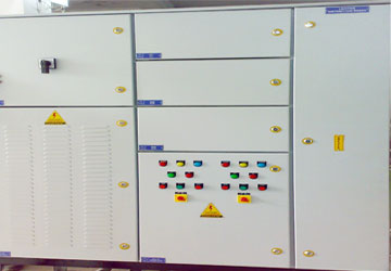
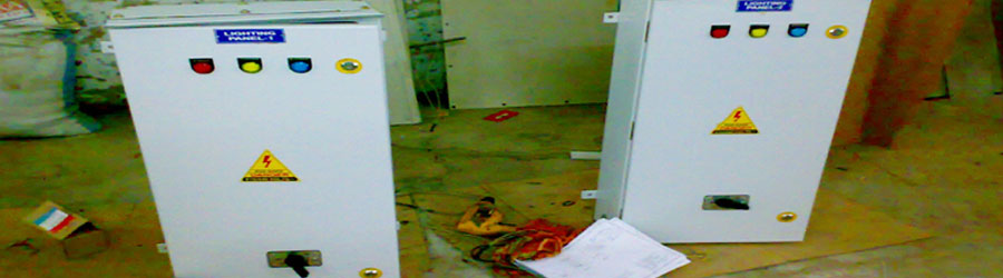
Powder Coating. Paint color of your choice as per IS-5 1978 with latest amendment. Danger notice plate shall also be provided.
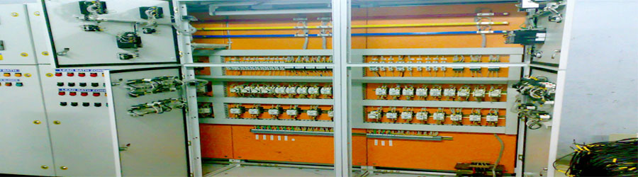
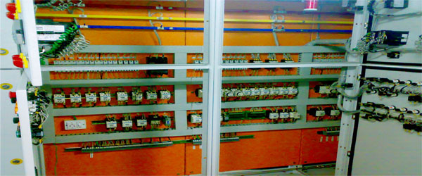
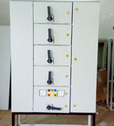
A front framed structure of rolled/folded sheet steel channel section of minimum 2 mm thickness, rigidly bolted together. This structure shall house the component contributing to the major weight of the equipment such as SFU’s, Contactors, Overload relay etc.The design ensure that the weight of the components is adequately supported without deformation or loss of alignment during transit or during operation.
Front door shall be fitted with dust excluding neoprine gasket with fastner designed to ensure proper compression of the gaskets. When covers are provided in place of doors, generous overlap shall be assured between sheet steel surfaces with closely fasteners to Preclude the entry of dust.
|
Doors and covers shall be of minimum 2 mm thick CRCA sheet steel. Shrouds shall be of FRP material. All sheet steel work forming the exterior of switch board shall be smoothly Finished, leveled and free from flaws. The corners are rounded.
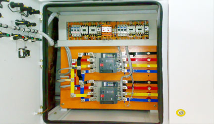
All Bus Bar supports used in the panels are S.M.C type non hygroscopic suitable to with
Stand required fault level.
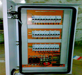
The equipment and circuits in the panel shall be so arranged as to facilitate their operation and maintenance and at the same time to ensure the necessary degree of safety.
The equipment forming part of bus bar system shall have following clearances in the
Mains:
|
a) Between Phases - 25 mm |
b) Between Phase and Neutral - 25 mm |
c) Between Phase and Earth - 25 mm |
d) Between Neutral and Earth - 25 mm |
When for any reason, the above clearance is not available, suitable insulation shall be
provided to increase the creep age distances, clearances shall be maintained during normal service conditions, creep age distances shall comply to those specified in relevant
standards.
All insulating material used in the construction of the equipment shall be non hygroscopic material, duly treated to withstand the effects of high humidity, high temperature tropical ambient service conditions.
|
The SFU’S/MCCB’S shall be of the load break, heavy duty, cubical type confirming to latest IS. The SFU/MCCB shall be provided with a front operating handle with a marking of ON/OFF positions. Interlocks shall be provided so as to prevent opening of the unit door when switch in the ON position and also to prevent closing of the SFU with door
not properly secured. It should however, be possible for a competent examiner to operate the SFU/MCCB with the door open by releasing the interlock. The handle of the switch should be suitable for locking the SFU/MCCB switch in the OFF position by means of a padlock. The SFU/MCCB shall be cubicle mounted.
|
Routine tests shall be conducted in accordance with IS: 8623 and shall comprises: |
• Inspection of panel including inspection of wiring and electrical operational tests where necessary. |
• Dielectric tests. |
• Checking of protective measures and electrical continuity of the protective circuits. |
| |